
Ether Dream - Developer Manual
NOTE - This page is for the previous Ether Dream 1. Check the current website.
Contents
Introduction
This is a work-in-progress developer-oriented guide to the hardware features and software architecture of the Ether Dream DAC. For setup and usage tips, see the User Guide.
Hardware
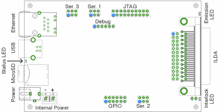
Starting at the Ethernet connector on the board and moving counterclockwise, the hardware features and connectors on the board are:
- Ethernet connector - includes link and activity LEDs
- USB connector. This is currently used only for firmware upgrades.
- Status LED. This LED blinks when the board is in bootloader mode, and is on normally.
- MicroSD slot. This will be used, in future software updates, for settings and playback of stored shows.
- External power jack. This is a 2.1mm/5.5mm barrel connector, center-positive, accepting 8V-25V DC.
- Power supply screw terminals. Ground is on the left (towards the outside of the board), positive is on the right (towards the inside of the board). The two power inputs are isolated from one another with diodes; if both are connected, power will be drawn only from the one with the higher voltage.
- GPIO header. This connects extra pins from the microcontroller. Pin 1 is closest
to the power jack. The pinout is:
1 - P1[8] / PWM1[1] / CAP1[0] 2 - +5.5v supply 3 - P1[19] / MCOA0 / CAP1[1] 4 - P1[22] / MCOB0 / MAT1[0] 5 - P1[26] / MCOB1 / PWM1[6] / CAP0[0] 6 - P1[29] / MCOB[2] / PCAP1[1] / MAT0[1] 7 - +3.3v supply 8 - P0[15] / TXD1 / SCK0 / SCK 9 - ground 10 - P0[17] / CTS1 / MISO0 / MISO 11 - P0[18] / DCD1 / MOSI0 / MOSI 12 - P0[16] / RXD1 / SSEL0 / SSEL - Serial header #2. Pinout:
1 - P0[10] / TXD2 / SDA2 / MAT3[0] 2 - +5.5v supply 3 - P0[11] / RXD2 / SCL2 / MAT3[1] 4 - +3.3v supply 5 - P1[28] / MCOA2 / PCAP1[0] / MAT0[0] 6 - ground - Interlock LED (yellow). This LED is on whenever the interlock relay is closed.
- ILDA DB-25 connector.
- Behind the DB-25 connector: 2x13 pin header wired identically to the DB-25.
- Emission LED (green). Whenever the DAC is producing output, this LED is on.
- 20-pin ARM JTAG header. Pin 1 is towards the power connectors.
- 1x6 pin serial debug header. This is intended to be used for debug purposes with a
TTL serial adapter, such as this unit
available from sparkfun. Pin 1 is closest to the Ethernet connector. The pinout is:
1 - P2[10]/EINT0/NMI 2 - P0[2] / TXD0 / AD0[7] 3 - P0[3] / RXD0 / AD0[6] 4 - unconnected 5 - unconnected 6 - ground - Serial header #1. Pinout:
1 - P2[0] / PWM1[1] / TXD1 2 - +5.5v supply 3 - P2[1] / PWM1[2] / RXD1 4 - +3.3v supply 5 - P2[2] / PWM1[3] / CTS1 6 - ground - Serial header #3. Pinout:
1 - P0[25] / AD0[2] / I2SRX_SDA / TXD3 2 - +5.5v supply 3 - P0[26] / AD0[3] / AOUT / RXD3 4 - +3.3v supply 5 - P2[3] / PWM1[4] / DCD1 6 - ground
Configuration
The Ether Dream requires no network configuration. By default, it will attempt to acquire an IP address with DHCP; if no DHCP server is found, it will instead choose a link-local 169.254.x.x address. Once it has an address, it will begin advertising its presence with UDP broadcast packets on port 7654. The playback DLL looks for these broadcasts to find DACs on the network.
Protocol
Protocol documentation is here.
Drivers are available for Windows and Mac/Linux.
Development
The Ether Dream firmware, available on github, builds on a standard Linux system with the free CodeSourcery ARM toolchain. The README in the repository describes the needed tools.Firmware Updates
There are three ways of updating the Ether Dream's firmware:- USB
The Ether Dream board comes with a USB bootloader in the first 16kB of Flash. (Source for the bootloader is in the boot/ directory of the source tree.) This bootloader implements the standard DFU protocol; the dfu-util project provides a PC-side tool.
The bootloader runs on every power-up, but normally immediately jumps to the main firmware. If the firmware is corrupt or the DAC has been forced into bootloader mode, it will instead run and appear as a USB DFU device. This mode is indicated by the LED next to the USB connector flashing rapidly. There are two ways to force the DAC to run in bootloader mode:
- Hold P0[18] low during power-on.
- Send a special USB control request while the normal firmware is running. There is a tool to do this in the source repository.
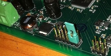
The pin to force bootloader mode, P0[18], is located next to a ground pin on the 2x6 expansion header. Connect a jumper across these pins and then apply power to run the bootloader.
On the host PC, if dfu-util is installed, running "make bl" in the firmware directory will automatically update the firmware of an attached DAC. Either force the DAC into bootloader mode and run "make bl", or "make bl" while the DAC is running its usual firmware; in the latter case, the DAC will be rebooted into bootloader mode and then updated.
- Serial
There is a built-in ROM bootloader on the LPC1758 which runs over UART0, connected to the 1x6 header on the board. It enters if P2[10] is held low when power is applied. When the ROM bootloader is running, both LEDs on the board will be very dimly lit. The lpc21isp tool talks to the DAC in this mode.
P2[10] on the LPC1758 is connected to RTS on the 6-pin serial header. Running "make flash" in the firmware directory and then applying power to the DAC will update the firmware and USB bootloader over serial.
This method is somewhat slower than the USB bootloader and so is not generally recommended - it is useful primarily for installing the firmware into a previously-unprogrammed DAC. Also, note that the 6-pin serial header is logic-level; it is 5-volt-tolerant but must not be connected directly to an RS-232 port.
- JTAG
The LPC1758 Flash can be reprogrammed over JTAG with openocd. See the user's manual for the microcontroller and the openocd documentation for details.